Welcome to Aluleader Metal
How to Connect Aluminum Extrusions: Methods, Fasteners & Best Practices
Aluminum extrusions are widely used to build machine frames, industrial workstations, equipment enclosures, furniture structures, automation systems, and custom assemblies.
One of their main advantages is the ability to create lightweight, modular structures using different joining methods.
However, choosing the correct connection is just as important as selecting the aluminum profile itself.
A poorly designed joint can cause frame movement, misalignment, loosening, or premature failure, even when the extrusion has sufficient strength for the application.
The most common ways to connect aluminum extrusions include corner brackets, T-slot nuts and bolts, internal connectors, end fasteners, joining plates, and welding. The best method depends on the profile geometry, loading conditions, assembly requirements, and whether the structure needs to be adjusted or disassembled.
This guide explains the main aluminum extrusion joining methods, how common connectors work, and what engineers and buyers should consider when designing reliable aluminum profile assemblies.
1. Why Aluminum Extrusion Connections Matter
An aluminum extrusion frame is a system of interconnected components.
Its performance depends on more than the strength of the individual profiles.
Connections influence:
Overall frame stiffness
Alignment and dimensional accuracy
Resistance to vibration
Assembly and installation time
Maintenance requirements
Ability to modify the structure
Long-term reliability
For example, a machine frame assembled using suitable connectors may provide good stability while remaining easy to modify.
However, if the joints are not designed for the applied loads, the structure may experience unwanted movement.
Connection Strength vs Profile Strength
An aluminum extrusion may have sufficient bending strength for a particular application, but the connection between two profiles can still become the limiting factor.
Joint performance depends on:
Connector geometry
Fastener size and grade
Tightening and preload
Profile slot or wall geometry
Contact surfaces
Load direction
Repeated or dynamic loading
This is why connection design should be evaluated as part of the complete assembly.
Not All Aluminum Profiles Use the Same Connectors
Industrial T-slot profiles are designed to accept compatible fastening accessories.
Architectural profiles, furniture profiles, tubes, and custom extrusions may require different joining methods.
A connector designed for a 40 mm industrial framing system is not automatically suitable for every aluminum profile with a nominal 40 mm dimension.
Always confirm compatibility with the actual cross-sectional drawing.
2. Main Methods for Connecting Aluminum Extrusions
Several joining methods are commonly used in aluminum extrusion assemblies.
Each offers different advantages and limitations.
| Joining method | Typical applications | Main advantages | Key considerations |
|---|---|---|---|
| Corner brackets | Machine frames, workstations | Accessible and adjustable | Space, appearance, joint stiffness |
| T-nuts and bolts | T-slot framing systems | Modular and reusable | Slot compatibility, tightening |
| Internal connectors | Industrial frames, visible structures | Concealed appearance | Installation access, profile compatibility |
| End fasteners | Profile-to-profile joints | Compact connections | End preparation, thread engagement |
| Joining plates | Frame reinforcement, extensions | Flexible joint configurations | Plate thickness, fastener arrangement |
| Welding | Permanent fabricated assemblies | No removable mechanical fasteners at the joint | Heat effects, distortion, inspection |
| Adhesive bonding | Selected lightweight assemblies | Distributed load transfer, no visible fasteners | Surface preparation, environment, validation |
There is no universally strongest or most economical joining method.
The correct choice depends on the intended application and verified joint performance.
3. Connecting Aluminum Extrusions With Corner Brackets
Corner brackets are among the most common connectors used in modular aluminum framing.
They are typically mounted at the intersection of two profiles and secured with bolts or other suitable fasteners.
How Corner Brackets Work
A corner bracket provides a mechanical connection between profiles, often at a 90-degree angle.
The bracket transfers loads through its geometry, fasteners, and contact with the profiles.
Common arrangements include:
External 90-degree brackets
Reinforced angle brackets
Gusseted corner brackets
Adjustable-angle brackets
Multi-hole connection brackets
Advantages of Corner Brackets
Corner brackets are popular because they are generally easy to install and inspect.
They may offer:
Straightforward assembly
Easy replacement
Accessible fasteners
Adjustment during installation
Compatibility with many modular systems
They are often suitable for workstations, guards, equipment frames, and general-purpose structures.
Limitations of Corner Brackets
External brackets occupy space around the joint.
This may interfere with panels, doors, covers, or adjacent components.
Their appearance may also be unsuitable for applications requiring concealed connections.
More importantly, the stiffness and strength of a bracketed joint depend on the complete connection design.
When Should You Use Reinforced Brackets?
Reinforced or gusseted brackets may be appropriate where a joint requires greater resistance to rotation or other applied loads.
However, a larger bracket does not automatically guarantee sufficient capacity.
The bracket, fasteners, profile geometry, and load conditions must be evaluated together.
4. Connecting T-Slot Aluminum Extrusions With T-Nuts and Bolts
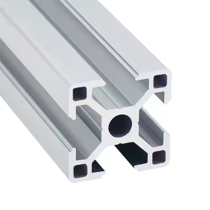
T-slot aluminum extrusion systems are designed around longitudinal slots that accept compatible connectors and accessories.
T-nuts and bolts are among the most widely used fastening components in these systems.
What Is a T-Slot Aluminum Extrusion?
A T-slot profile contains specially shaped grooves along its length.
These grooves allow suitable nuts or fastening elements to engage with the profile.
The system can be used to mount brackets, panels, accessories, and other profiles.
Common applications include:
Industrial workstations
Automation equipment
Machine guards
Modular frames
Assembly fixtures
Equipment supports
How T-Nuts Work
A T-nut engages with the internal geometry of the profile slot.
A bolt passes through the connected component and threads into the nut.
When tightened correctly, the fastener clamps the components together.
Depending on the system, T-nuts may be inserted from the end of the profile or installed through the slot opening.
Common Types of T-Slot Nuts
Slide-in T-nuts: Typically inserted from the end of a compatible profile slot.
Drop-in or roll-in nuts: Designed for installation through the slot opening in compatible systems.
Spring-loaded nuts: May use a spring or retaining feature to help position the nut during assembly.
Different manufacturers use different designs and terminology.
T-Slot Compatibility Is Essential
T-slot profiles are not universally interchangeable.
Even when two profiles have the same nominal outside dimensions, they may differ in:
Slot opening width
Slot depth
Internal slot geometry
Nut seating surfaces
Threaded accessory requirements
Series-specific dimensions
For example, two nominal 40 × 40 mm profiles may require different fastening accessories.
Always match the T-nut and bolt to the actual profile series, not just the outside dimensions.
Selecting the Correct Bolt
Bolt selection depends on the connection design.
Important factors include:
Thread diameter
Thread pitch
Bolt length
Bolt grade
Required engagement
Washer or spacer requirements
Tightening procedure
Using an incorrect bolt length can result in insufficient engagement or bottoming out before proper clamping is achieved.
For critical connections, follow the fastener and connector manufacturer's specifications.
5. Hidden and Internal Aluminum Extrusion Connectors
Internal connectors are used when a cleaner appearance or reduced external hardware is desired.
These connectors are often installed inside the profile or within specially designed connection features.
Why Use Hidden Connectors?
Potential advantages include:
Reduced visible hardware
Cleaner external appearance
Less interference with surrounding components
Compact joint design
Suitable integration into modular systems
Internal connectors are commonly used in industrial framing and selected furniture or display applications.
Common Internal Connector Designs
Depending on the extrusion system, internal connections may use:
Anchor-style fasteners
Internal joining elements
Concealed corner connectors
Profile-specific locking mechanisms
End-mounted connectors
These systems are not universally compatible.
Some require special holes, machining, or installation tools.
Internal Connector Limitations
Hidden connectors may be more difficult to inspect or access after assembly.
They may also require precise installation procedures.
For load-bearing frames, the designer should verify the connector's capacity and stiffness.
A concealed connection should not be selected solely for appearance when structural performance is important.
6. End-to-End Aluminum Extrusion Connections
Sometimes two aluminum profiles must be connected along the same axis to create a longer assembly.
This is commonly called an end-to-end or inline connection.
Common Methods
Possible approaches include:
Internal joining plates
Profile-specific inline connectors
External splice plates
Mechanical fastening through prepared ends
Welding, where appropriate
Important Design Considerations
An inline connection may experience bending, tension, compression, shear, or torsion.
The joining method should be selected according to the actual load conditions.
A simple connector may be suitable for positioning or alignment but insufficient for a highly loaded structural member.
Avoid Assuming Full Strength Continuity
Joining two profiles end-to-end does not automatically create a member with the same strength and stiffness as a continuous extrusion.
The joint may introduce local flexibility or become the limiting section.
For critical applications, use engineering calculations, verified connector data, or appropriate testing.
7. Joining Aluminum Extrusions With Plates and Gussets
Joining plates provide another flexible method for assembling aluminum profiles.
They may be used to connect profiles at corners, intersections, or along their length.
Flat Joining Plates
Flat plates are commonly used for:
Inline connections
Frame extensions
Reinforcing joints
Attaching additional components
The plate is typically secured using suitable mechanical fasteners.
Gusset Plates
Gussets can help reinforce certain frame joints by increasing the effective connection geometry.
They may be particularly useful where a joint must resist rotation.
Plate Design Considerations
Important factors include:
Plate material
Plate thickness
Fastener spacing
Hole dimensions
Edge distances
Load direction
Connection accessibility
A plate should be designed for the required forces rather than selected only by appearance.
8. Can Aluminum Extrusions Be Welded?
Yes. Many aluminum extrusion alloys can be welded using appropriate procedures.
Welding creates a permanent metallurgical joint between compatible components.
However, weldability and post-weld properties depend on the alloy, temper, joint design, and welding process.
Common Welding Methods
Depending on the application, aluminum extrusions may be joined using processes such as:
Gas tungsten arc welding (GTAW/TIG)
Gas metal arc welding (GMAW/MIG)
Other specialized welding processes
The correct process depends on material thickness, joint geometry, production requirements, and applicable standards.
Welding 6061-T6 Aluminum
6061-T6 is used in many industrial applications.
However, welding can significantly reduce strength in the heat-affected zone.
The original T6 mechanical properties should not be assumed to remain unchanged near the weld.
For structural applications, joint design and allowable properties must account for welding effects.
Welding 6063 Aluminum
6063 aluminum can also be welded using suitable procedures.
However, the welding process may affect local properties and appearance.
If the finished assembly requires anodizing or another decorative treatment, the appearance of welded areas should be considered.
Advantages of Welding
Welding may offer:
Permanent connections
No separate mechanical fasteners at the welded joint
Flexibility for certain fabricated structures
Suitability for selected custom assemblies
Limitations of Welding
Potential concerns include:
Heat-induced distortion
Changes in mechanical properties
Surface finishing differences
Inspection requirements
Reduced ease of disassembly
Need for suitable welding procedures
For modular frames that require frequent adjustment, mechanical fastening may be more practical.
9. Adhesive Bonding for Aluminum Extrusion Assemblies
Adhesive bonding is another possible joining method for selected aluminum components.
It may be useful when mechanical fasteners are undesirable or when the joint geometry supports adhesive load transfer.
Potential Advantages
Adhesive bonding can provide:
Distributed load transfer across a bonded area
Reduced visible fastening hardware
Potential isolation between dissimilar materials
Design flexibility for certain assemblies
Important Limitations
Adhesive performance depends on:
Surface preparation
Adhesive chemistry
Joint geometry
Temperature
Moisture and environmental exposure
Loading duration and direction
Manufacturing process control
Adhesive joints should be validated for their intended service conditions.
For critical applications, do not substitute an adhesive connection for a designed mechanical joint without appropriate engineering assessment.
10. How to Build a Strong Aluminum Extrusion Frame
A reliable aluminum extrusion frame requires suitable profiles, connectors, and assembly practices.
The following process provides a practical starting point.
Step 1: Define the Frame Requirements
Identify the frame's intended use.
Consider:
Static loads
Dynamic loads
Vibration
Overall dimensions
Required stiffness
Environmental conditions
Maintenance requirements
A simple display frame and a heavily loaded machine structure may require very different connection designs.
Step 2: Choose the Aluminum Profile
Select the profile geometry, alloy, and temper according to the application.
For industrial structures, consider both the profile's mechanical properties and the available connection system.
Our guide to aluminum extrusion profile types and sizes explains common profile families and selection considerations.
Step 3: Select Compatible Connectors
Choose connectors designed for the profile series.
Check slot dimensions, fastener requirements, and installation procedures.
Do not assume that accessories from different framing systems are interchangeable.
Step 4: Prepare the Profile Ends
Depending on the connection method, the profiles may require cutting, drilling, tapping, or other preparation.
Cutting accuracy is important because uneven ends can affect frame alignment and contact between components.
Step 5: Assemble on a Suitable Surface
Use an appropriate assembly surface and verify alignment.
For rectangular frames, check dimensions and diagonals as applicable.
Step 6: Tighten Fasteners Correctly
Follow the connector and fastener manufacturer's installation requirements.
Avoid using arbitrary tightening torque values.
The appropriate torque depends on fastener size, grade, lubrication, thread engagement, connector design, and the material being clamped.
Overtightening may damage threads or deform the profile.
Insufficient tightening may allow the connection to loosen or move.
Step 7: Verify Alignment and Stability
After assembly, inspect the frame for:
Correct dimensions
Proper joint seating
Alignment
Loose components
Unexpected movement
Interference with other parts
Step 8: Validate the Structure
For load-bearing or safety-related applications, verify that the complete frame meets its design requirements.
This may require engineering calculations, manufacturer connector data, or physical testing.
11. How to Prevent Aluminum Extrusion Joints From Loosening
Joint loosening can occur when a connection experiences vibration, cyclic loading, inadequate preload, or unsuitable installation.
Prevention begins with correct connection design.
Use Appropriate Fasteners
Select fasteners that meet the required mechanical and dimensional specifications.
Follow the Correct Tightening Procedure
Proper preload is important for many bolted joints.
Use the recommended tightening method and torque where specified.
Consider Vibration
Equipment frames exposed to vibration may require additional design measures.
Depending on the connection system, these may include suitable locking features or other verified methods.
Check Contact Surfaces
Poor contact or misalignment can reduce joint reliability.
Ensure the connected surfaces and components are suitable for the intended assembly.
Plan Inspection and Maintenance
For equipment subject to repeated loading, establish appropriate inspection and maintenance procedures.
The required frequency depends on the application and operating conditions.
12. Aluminum Extrusion Connection Design for Different Applications
Different applications place different demands on joining methods.
Industrial Automation Frames
Industrial automation systems often use modular T-slot profiles.
Common joining methods include corner brackets, internal connectors, and T-nut assemblies.
Key considerations include:
Equipment loads
Vibration
Frame stiffness
Accessory compatibility
Ease of modification
Machine Guards and Enclosures
Machine guards may use aluminum profiles with panels and doors.
Connections must support the guard's intended function and applicable safety requirements.
A modular connection may simplify maintenance, but the complete guarding system must be properly designed.
Furniture and Display Structures
Furniture and display applications may prioritize:
Appearance
Compact connections
Ease of assembly
Surface protection
Compatibility with panels
Hidden connectors may be useful, but their suitability depends on the structure.
Architectural Frames
Architectural aluminum profiles may use specialized corner joints, mechanical fasteners, crimping arrangements, or other system-specific connections.
These methods should not be confused with standard industrial T-slot accessories.
For window and door applications, joint performance depends on the complete system design, including sealing, hardware, drainage, and relevant testing.
Solar and Outdoor Structures
Outdoor aluminum structures may require particular attention to:
Wind and other environmental loads
Corrosion exposure
Fastener compatibility
Thermal movement
Drainage
Long-term connection performance
The joining method should be selected according to the applicable engineering requirements.
13. Common Mistakes When Connecting Aluminum Extrusions
Mistake 1: Using Incompatible T-Slot Accessories
Similar-looking profiles may have different slot geometries.
Always verify accessory compatibility.
Mistake 2: Selecting Connectors Based Only on Appearance
A compact or hidden connector may not provide the required structural performance.
Evaluate the connection under the intended loads.
Mistake 3: Ignoring Joint Stiffness
A connection may remain intact but still allow excessive movement.
For precision equipment, stiffness can be as important as strength.
Mistake 4: Using Incorrect Bolt Lengths
Bolts that are too short may have insufficient engagement.
Bolts that are too long may interfere with the assembly or prevent proper clamping.
Mistake 5: Overtightening Fasteners
Excessive tightening can damage threads, connectors, or profile features.
Use appropriate installation specifications.
Mistake 6: Ignoring Welding Effects
Welding precipitation-hardened aluminum can change mechanical properties near the joint.
Account for these changes in structural design.
Mistake 7: Failing to Validate the Assembly
A frame that appears rigid during initial assembly may behave differently under operating loads or vibration.
Verify the finished structure according to its intended use.
14. Aluminum Extrusion Connectors: Selection Checklist
Before selecting a connection method, review the following factors.
| Requirement | Question to ask |
|---|---|
| Profile compatibility | Does the connector fit the exact profile series? |
| Joint geometry | Is the connection inline, perpendicular, angled, or otherwise configured? |
| Load conditions | What forces and moments will the joint experience? |
| Stiffness | How much joint movement is acceptable? |
| Assembly | Can the connector be installed correctly? |
| Maintenance | Does the joint need to be disassembled? |
| Appearance | Must the connection be concealed? |
| Environment | Will corrosion, moisture, or temperature affect the joint? |
| Vibration | Is additional loosening resistance required? |
| Documentation | Are installation instructions and performance data available? |
For structural or safety-related applications, connector selection should be supported by suitable engineering information.
15. What to Include When Ordering Aluminum Profiles and Connectors
When requesting aluminum extrusions for an assembly, provide more than the outside profile dimensions.
Useful information includes:
Profile drawing or exact catalog series
Aluminum alloy and temper
Profile dimensions and cut lengths
Slot dimensions, where applicable
Required connector type
Fastener specifications
Quantity of profiles and connectors
Required machining or tapping
Surface finish
Intended application
Relevant loading and assembly requirements
Request Matching Accessories
If purchasing a modular framing system, confirm that the supplier can identify suitable connectors and accessories for the specified profile.
Do not assume that every extrusion manufacturer supplies every type of bracket, T-nut, or internal connector.
Confirm Processing Requirements
Some connection methods require drilled holes, tapped ends, or other preparation.
Identify these operations before requesting a final quotation.
Evaluate Total Assembly Cost
A profile with a lower unit price may require more machining or additional connectors.
Another profile may incorporate connection features that reduce assembly work.
Compare the cost of the complete assembly rather than the extrusion alone.
For further information on profile design and manufacturability, see our custom aluminum extrusion design guide.
16. Frequently Asked Questions
What is the easiest way to connect aluminum extrusions?
For compatible modular T-slot systems, corner brackets with suitable T-nuts and bolts are often a straightforward option. The best method depends on the profile and assembly requirements.
Can aluminum extrusions be connected without welding?
Yes. Aluminum extrusions can be joined using brackets, bolts, T-nuts, internal connectors, joining plates, and other mechanical fastening systems.
What are T-slot aluminum extrusion connectors?
T-slot connectors are accessories designed to engage with the slots of compatible aluminum framing profiles. They include T-nuts, brackets, internal fasteners, and other joining components.
Are all aluminum extrusion connectors interchangeable?
No. Connector compatibility depends on slot geometry, profile series, fastener specifications, and manufacturer design.
How do you connect two aluminum extrusions at 90 degrees?
Common methods include corner brackets, internal connectors, and profile-specific end fasteners. The appropriate method depends on load, stiffness, accessibility, and appearance requirements.
How do you connect aluminum extrusions end-to-end?
Inline connectors, joining plates, splice arrangements, or welding may be used. The joint must be evaluated for the intended loads and required stiffness.
Are hidden connectors stronger than corner brackets?
Not necessarily. Strength and stiffness depend on the specific connector, profile, fasteners, installation, and load direction. A comparison requires relevant performance data.
Can 6061-T6 aluminum extrusions be welded?
Yes, using suitable welding procedures. However, welding can reduce strength in the heat-affected zone. Structural applications must account for this effect.
What bolts are used for aluminum extrusion frames?
Bolt type and size depend on the profile series and connector design. Metric bolts are common in many modular framing systems, but there is no universal bolt specification for all aluminum extrusions.
How do I stop aluminum extrusion joints from loosening?
Use compatible connectors, appropriate fasteners, correct tightening procedures, and suitable measures for vibration or cyclic loading. Follow the connector manufacturer's installation requirements.
Can I build a structural frame with T-slot aluminum extrusions?
T-slot profiles can be used in engineered frames, but suitability depends on loads, deflection, joint performance, and applicable safety requirements. Structural capacity should be verified.
Do custom aluminum extrusions require special connectors?
Not always. Some custom profiles can use standard fasteners, while others require dedicated connection features or custom components. Connector requirements should be considered during profile design.
Conclusion: Choose Aluminum Extrusion Connections Based on the Complete Assembly
Aluminum extrusions can be connected using brackets, T-nuts, bolts, internal connectors, joining plates, welding, and other suitable methods.
Each approach offers different advantages in terms of assembly, appearance, adjustability, and structural performance.
For modular industrial frames, compatible mechanical connectors are often convenient because they allow components to be assembled and modified.
For permanent fabricated structures, welding may be appropriate when the material, joint design, and manufacturing process are properly evaluated.
The most reliable aluminum extrusion connection is the one designed for the actual profile geometry, loading conditions, and service environment.
Before selecting connectors, confirm compatibility, installation requirements, and the performance of the complete assembly.
Discuss Aluminum Extrusion Profiles for Your Project With ALULEADER
If you are sourcing aluminum profiles for industrial frames, equipment structures, furniture systems, or custom assemblies, ALULEADER can be contacted to discuss your requirements.
Explore our industrial aluminum profiles and structural aluminum profile products.
For projects requiring application-specific slots, channels, or connection features, review our custom aluminum extrusion design guide.
Send your profile drawing, intended application, required dimensions, assembly details, and estimated order quantity to ALULEADER for a technical feasibility review and quotation.