Welcome to Aluleader Metal
Custom Aluminum Extrusion Design Guide: Alloys & Tolerances
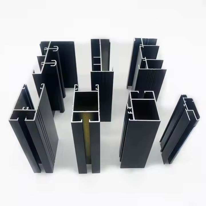
Custom aluminum extrusion allows engineers and manufacturers to create profiles with cross-sectional shapes designed for specific applications. From industrial machine frames and electronic enclosures to architectural systems and furniture components, a well-designed aluminum extrusion can combine multiple functions into a single part.
However, designing a custom aluminum profile involves more than creating a cross-sectional drawing.
The aluminum alloy, temper, wall thickness, internal geometry, dimensional tolerances, surface finish, and manufacturing process all influence whether a profile can be produced consistently and economically.
The key to successful custom aluminum extrusion design is to balance product performance with extrusion manufacturability. A profile should meet its functional requirements without introducing unnecessary tooling complexity, difficult tolerances, or avoidable production costs.
This guide explains how to design custom aluminum extrusion profiles, select suitable alloys, optimize wall thickness, specify tolerances, and prepare drawings for manufacturing.
It is intended for product engineers, industrial designers, fabricators, purchasing managers, and businesses developing custom aluminum components.
1. What Is Custom Aluminum Extrusion Design?
Custom aluminum extrusion design is the process of developing a profile with a specific cross-sectional geometry for a particular product or application.
During manufacturing, a heated aluminum billet is forced through a shaped die to create a continuous profile.
The resulting extrusion maintains approximately the same cross-sectional shape along its length, subject to manufacturing tolerances.
This process makes it possible to incorporate functional features directly into the aluminum profile.
Examples include:
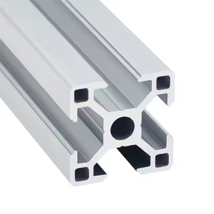
Mounting channels and screw ports
Internal reinforcement ribs
Sliding tracks and guide rails
Cable management channels
Panel retention grooves
Decorative external surfaces
Hollow chambers for weight reduction
Connection features for other components
By integrating these features into one profile, manufacturers may reduce the number of separate components and assembly operations.
However, not every shape that can be modeled in CAD is practical to extrude.
The design must account for metal flow through the die, tooling feasibility, profile distortion, cooling, and dimensional control.
Standard vs Custom Aluminum Extrusions
Standard aluminum profiles are based on existing designs, such as common angles, channels, tubes, and industrial framing sections.
Custom profiles are developed around specific product requirements.
| Consideration | Standard aluminum profiles | Custom aluminum extrusions |
|---|---|---|
| Cross-section | Existing profile design | Application-specific geometry |
| Tooling | May use an existing die | Often requires a new die |
| Design flexibility | Limited to available options | Greater flexibility |
| Initial development | Usually simpler | Requires engineering review |
| Component integration | May require additional parts | Can integrate multiple functions |
| Suitable applications | General-purpose assemblies | Specialized products and repeat manufacturing |
Before investing in a custom extrusion die, check whether an existing profile can meet the application's functional requirements.
Our guide to aluminum extrusion profile types and sizes explains the differences between common profile shapes and standard product families.
2. Define the Application Before Designing the Profile
A successful extrusion design begins with understanding how the finished component will be used.
The same cross-sectional shape may perform differently depending on the alloy, temper, load conditions, environment, and assembly method.
Before developing the drawing, answer the following questions:
What function must the profile perform?
Will it carry structural loads?
Does it need to fit other components?
Will it be used indoors or outdoors?
Is surface appearance important?
Does it require machining or additional processing?
What is the expected production quantity?
Are there applicable product or industry standards?
These requirements help determine which design features are necessary.
Example: Industrial Equipment Frame
An industrial frame may require mounting slots, reliable mechanical connections, and sufficient stiffness.
The designer should consider profile geometry, loading, connection strength, and assembly requirements.
Example: Architectural Window Profile
A window or door profile may need grooves for seals, glazing, rollers, hardware, and other system components.
Its dimensions must be compatible with the complete window or door assembly.
The profile's wall thickness and alloy alone do not establish the performance of the finished window system.
Example: Furniture Aluminum Profile
A furniture profile may prioritize surface appearance, lightweight construction, panel retention, and ease of assembly.
Decorative requirements may influence the choice of alloy and surface treatment.
Designing around the actual application helps prevent unnecessary features and expensive manufacturing changes.
3. Aluminum Extrusion Alloy Selection Guide
Choosing the correct aluminum alloy is one of the most important decisions in custom extrusion design.
Different alloys offer different combinations of strength, extrudability, corrosion resistance, machinability, and finishing characteristics.
Among the commonly used extrusion alloys are 6063, 6061, and 6005A.
6063 Aluminum for Custom Extrusions
6063 is widely used for architectural and decorative aluminum profiles.
It is often selected for applications requiring relatively complex cross-sections and attractive surface finishes.
Common applications include:
Window and door frames
Architectural trim
Furniture components
Decorative channels
General-purpose custom profiles
6063 is frequently supplied in T5 or T6 temper, depending on the required properties and production conditions.
Learn more in our guide to 6063 aluminum window and door profiles.
6061 Aluminum for Custom Extrusions
6061 is commonly used for industrial and structural applications.
In suitable tempers, it offers useful mechanical properties and machinability.
Typical applications include:
Industrial equipment components
Structural mounting sections
Transportation parts
Machine components
Fabricated assemblies
However, some intricate or thin-wall designs may be more difficult to extrude in 6061 than in 6063.
The appropriate alloy should be selected after considering both the finished component's performance requirements and the proposed cross-section.
6005A Aluminum Extrusions
6005A is another alloy used in structural extrusion applications.
It may be considered for certain frames and structural sections, depending on the required mechanical properties and manufacturing specifications.
Aluminum Extrusion Alloy Comparison
| Alloy | General characteristics | Typical applications | Design considerations |
|---|---|---|---|
| 6063 | Good extrudability and surface finish potential | Architectural and decorative profiles | Suitable for many complex profile designs |
| 6061 | Useful strength and machinability in suitable tempers | Industrial and structural components | Geometry and extrusion difficulty require review |
| 6005A | Used in various structural extrusion applications | Frames and structural sections | Availability and temper requirements should be confirmed |
This comparison is intended for preliminary material selection.
Actual mechanical properties depend on the alloy, temper, product dimensions, and applicable material specification.
Why Aluminum Temper Matters
The temper designation describes the material's processing condition.
For example:
6063-T5
6063-T6
6061-T6
These designations identify different material conditions and should not be treated as interchangeable.
The specified temper can affect mechanical properties and manufacturing requirements.
When preparing an RFQ, include both the alloy and the required temper.
If the appropriate temper is uncertain, discuss the application and performance requirements with the manufacturer before finalizing the specification.
4. How to Design Aluminum Extrusion Wall Thickness
Wall thickness influences material consumption, weight, structural behavior, and extrusion feasibility.
For custom aluminum profiles, selecting the correct wall thickness requires balancing performance and manufacturability.
Why Wall Thickness Matters
A thicker wall generally increases the amount of aluminum in a profile, but the relationship between wall thickness and structural performance is not always straightforward.
Cross-sectional geometry, load direction, support conditions, and material properties also matter.
In some designs, strategically positioned ribs or changes in section geometry may improve stiffness more efficiently than increasing the thickness of every wall.
However, any structural change should be evaluated against the actual loading conditions.
Maintain Reasonably Consistent Wall Thickness
Where practical, relatively consistent wall thickness can help simplify extrusion.
Large differences in wall thickness may affect metal flow through the die and increase manufacturing difficulty.
For example, a profile with a very thick base and extremely thin projecting walls may require additional design review.
This does not mean all walls must have identical thickness.
Some applications require local reinforcement or intentionally different wall sections.
The objective is to avoid unnecessary variations that make extrusion more difficult without improving product function.
Thin-Wall Aluminum Extrusion Design
Thin-wall aluminum extrusions can reduce material usage and weight.
They may be useful for:
Decorative architectural sections
Lightweight furniture components
Certain enclosure profiles
Specialized industrial components
However, thin walls can create manufacturing challenges.
Potential concerns include:
Difficulty maintaining dimensional consistency
Increased sensitivity to distortion
Complex die design
Damage during handling or machining
Reduced suitability for certain loading conditions
There is no universal minimum wall thickness for all custom aluminum extrusions.
The achievable thickness depends on the alloy, cross-sectional geometry, profile size, extrusion equipment, die design, and required tolerances.
For example, a 1.4 mm wall may be feasible in some architectural profile designs, but that does not mean every extrusion geometry can be manufactured reliably at 1.4 mm.
It also does not establish that 1.4 mm is a universal building-code requirement.
Practical Wall Thickness Design Checklist
Before finalizing wall thickness, consider:
Required structural performance
Alloy and temper
Overall profile size
Wall thickness distribution
Hollow chamber geometry
Critical assembly features
Surface finish requirements
Manufacturing feasibility
Target production cost
For more detailed guidance, read our aluminum profile wall thickness guide.
5. Design Hollow and Semi-Hollow Profiles Carefully
Aluminum extrusion profiles are commonly classified as solid, hollow, or semi-hollow.
The cross-sectional geometry influences the complexity of the extrusion die.
Solid Profiles
Solid profiles contain no completely enclosed internal cavities.
Examples include simple bars, angles, and certain channels.
These designs may be relatively straightforward to manufacture, although complex solid profiles can still present challenges.
Hollow Profiles
Hollow profiles contain one or more enclosed cavities.
Examples include square tubes, rectangular tubes, and multi-chamber structural profiles.
Producing hollow profiles generally requires tooling capable of forming the internal geometry.
The design must account for metal flow, internal features, and dimensional control.
Semi-Hollow Profiles
Semi-hollow profiles contain partially enclosed features that may require special tooling considerations.
Deep, narrow openings can make extrusion more difficult.
Avoid Unnecessarily Complex Internal Geometry
When developing a custom cross-section, review whether every internal rib, chamber, and groove is necessary.
Complex internal geometry may increase:
Tooling difficulty
Die manufacturing cost
Production sensitivity
Inspection requirements
Risk of dimensional variation
A simplified design may provide the same function with fewer manufacturing challenges.
However, removing structural ribs or other features should not be done without evaluating their functional importance.
6. Use Appropriate Corners, Radii, and Transitions
Sharp corners and abrupt changes in section geometry may create challenges in extrusion die design and metal flow.
Where the application allows, rounded transitions and suitable radii can improve design feasibility.
Internal Corners
Very sharp internal corners can be difficult to reproduce and may create local design or tooling concerns.
A suitable internal radius should be selected according to the profile geometry and functional requirements.
External Corners
External corners may also benefit from appropriate radii.
For visible architectural or furniture profiles, corner geometry can influence appearance and finishing results.
Transitions Between Thick and Thin Sections
Abrupt transitions between thick and thin walls may complicate metal flow and dimensional control.
Gradual transitions can sometimes improve manufacturability.
However, there is no single radius or transition ratio that is optimal for every extrusion.
The manufacturer should review the drawing and recommend changes based on the specific geometry.
7. Design Functional Features for Assembly
One advantage of custom aluminum extrusion is the ability to incorporate assembly features directly into the cross-section.
These may include screw ports, slots, guide channels, mounting surfaces, and panel-retention features.
Screw Ports
Screw ports can help accommodate certain fastening arrangements.
However, their geometry must be compatible with the selected fastener and intended assembly method.
Consider:
Screw diameter and engagement
Wall thickness around the port
Assembly loads
Repeated assembly requirements
Risk of local deformation
Mounting Slots
Mounting slots may be designed for bolts, sliding nuts, brackets, or other accessories.
Critical slot dimensions should be identified on the drawing.
A small dimensional difference can prevent the intended hardware from fitting correctly.
Sliding Channels and Guide Rails
Channels and tracks are commonly integrated into architectural and industrial profiles.
Important design considerations include clearance, alignment, surface finish, wear behavior, and compatibility with mating components.
Panel Retention Features
Custom profiles may incorporate grooves for glass, plastic panels, seals, or other components.
The design should account for the dimensions and tolerances of the mating parts.
Avoid Designing in Isolation
A profile should be evaluated as part of the complete assembly.
Where possible, test the extrusion with the actual fasteners, panels, seals, or other components it will use.
This is especially important for new designs that have not previously been manufactured.
8. Specify Aluminum Extrusion Tolerances Correctly
Dimensional tolerances define the acceptable variation between the drawing and the manufactured profile.
They are essential for custom extrusions that must fit other parts or meet specific functional requirements.
However, specifying unnecessarily tight tolerances can make production more difficult and potentially increase cost.
Common Dimensional Requirements
Custom aluminum extrusion drawings may specify tolerances for:
Overall width and height
Wall thickness
Internal openings
Slot dimensions
Angularity
Straightness
Twist
Flatness
Cut length
The appropriate limits depend on the profile design and applicable specification.
Standard Extrusion Tolerances
Recognized dimensional tolerance standards include EN 755-9 and ANSI H35.2, depending on the product and market.
These standards provide useful references, but their scope and requirements differ.
The relevant standard, edition, and acceptance criteria should be agreed upon before production.
Critical vs Noncritical Dimensions
Not every dimension requires the same precision.
For example, a decorative external surface may not require the same dimensional control as a narrow slot designed to accept a specific fastener.
A useful approach is to identify:
Critical dimensions: Features that directly affect assembly, fit, or function.
General dimensions: Features for which standard manufacturing tolerances may be acceptable.
Reference dimensions: Informational dimensions that should not be treated as independently controlled acceptance requirements.
This distinction helps manufacturers focus inspection and process control on the features that matter most.
Avoid Over-Tolerancing
Applying very tight tolerances to every dimension can increase manufacturing difficulty without improving the final product.
Instead, determine which dimensions require special control.
For complex assemblies, appropriate geometric dimensioning and tolerancing (GD&T) may help communicate functional requirements.
Example: Sliding Window Profile
A sliding window profile may contain several grooves and channels.
Some dimensions determine whether rollers, seals, or mating profiles fit correctly.
These functional dimensions may require particular attention during drawing review.
Other dimensions may be less critical.
For further information, see our aluminum extrusion tolerances guide.
9. Consider Surface Finishing During the Design Stage
Surface finishing should not be treated as an afterthought.
The intended finish may affect appearance, dimensional requirements, material selection, and manufacturing planning.
Common options include:
Mill finish
Anodizing
Powder coating
Brushing
Other application-specific treatments
Anodized Aluminum Extrusions
Anodizing is commonly used for architectural and decorative aluminum profiles.
The finished appearance depends on the alloy, extrusion surface condition, pretreatment, and anodizing process.
For visible products, the desired appearance should be specified and approved.
Powder Coated Aluminum Extrusions
Powder coating is widely used for decorative and protective applications.
The coating system should be selected according to the intended service environment.
When designing profiles with narrow openings or mating features, consider whether the finished coating dimensions could affect assembly.
Surface Appearance Requirements
Some profiles have highly visible surfaces, while others are concealed after installation.
Clearly identifying visible surfaces can help manufacturers understand cosmetic acceptance requirements.
If color consistency is important, request an approved reference sample before bulk production.
Our guide to powder coated vs anodized aluminum profiles explains the differences between these finishing methods.
10. Design for Secondary Machining and Fabrication
Many custom aluminum extrusions require additional processing after extrusion.
Common operations include:
Cutting to length
CNC machining
Drilling
Tapping
Milling
Punching
Countersinking
Assembly
These operations should be considered during the design stage.
Allow Access for Machining Tools
A profile with deeply recessed features may be difficult to machine.
Designers should consider whether cutting tools can access the required surfaces and whether the profile can be held securely during machining.
Consider Workholding
Thin-wall or irregularly shaped extrusions may require special fixtures to prevent movement or deformation during machining.
The location of clamping surfaces can influence manufacturing feasibility.
Coordinate Machining and Finishing
The sequence of machining and surface finishing can affect the final product.
For example, machining after anodizing may expose untreated aluminum surfaces.
Machining before finishing may be more appropriate for some applications, although the correct process depends on the design and functional requirements.
Avoid Unnecessary Processing
One of the potential advantages of custom extrusion is integrating features that would otherwise require separate machining or assembly.
However, attempting to incorporate every feature into the extrusion may make the die unnecessarily complex.
The best solution balances extrusion complexity with downstream processing requirements.
11. Understand Custom Aluminum Extrusion Die Design
A custom extrusion die determines the cross-sectional shape of the finished profile.
The die must be designed to produce the required geometry while supporting suitable metal flow and dimensional control.
Factors Affecting Die Complexity
Important considerations include:
Profile size
Solid or hollow geometry
Number of internal chambers
Wall thickness variation
Narrow slots and deep features
Required tolerances
Alloy selection
Surface quality requirements
A complex profile may require more extensive tooling development and trial adjustments.
Tooling Review Before Production
Before manufacturing a new die, the supplier should review the drawing for extrusion feasibility.
This review may identify features that are difficult to manufacture or dimensions that need clarification.
Potential design modifications should be discussed with the buyer.
Trial Extrusion and Die Correction
New dies may require trial extrusion to evaluate dimensional accuracy and surface quality.
Adjustments may be necessary before the profile meets the agreed specifications.
For this reason, tooling development and sample approval should be treated as separate stages from mass production.
Tooling Ownership and Maintenance
Commercial arrangements for custom dies vary.
Before placing an order, clarify:
Tooling charges
Ownership arrangements
Maintenance responsibilities
Modification costs
Future reorder arrangements
Conditions for tooling replacement
These terms should be documented rather than assumed.
12. How to Reduce Custom Aluminum Extrusion Costs Through Design
The cost of a custom extrusion depends on more than the price of aluminum.
Profile geometry, tooling, alloy, finishing, processing, and order quantity all affect manufacturing cost.
Good design can help control these factors.
Reduce Unnecessary Material
Excess material increases profile weight.
Where engineering requirements permit, designers may reduce unnecessary wall thickness or remove nonfunctional material.
However, material reduction must not compromise structural performance or assembly requirements.
Simplify the Cross-Section
A simpler cross-section may reduce tooling difficulty and improve manufacturing feasibility.
Evaluate whether complex grooves, internal chambers, or ribs are necessary.
Use Appropriate Tolerances
Unnecessarily tight tolerances can increase production and inspection requirements.
Specify precision where it affects function.
Select the Alloy Carefully
The lowest-cost alloy is not always the most economical choice.
A material that is difficult to extrude into the required geometry may create additional manufacturing challenges.
Evaluate material performance and production feasibility together.
Consider Total Manufacturing Cost
A more complex extrusion may reduce the need for separate machining or assembly.
Conversely, a simpler profile with limited secondary processing may be more economical for some applications.
The correct decision depends on total manufacturing cost rather than extrusion price alone.
Account for Production Quantity
Tooling charges can have a greater impact on the unit cost of a small order.
For repeat production, the initial tooling investment may be distributed across a larger number of parts.
When evaluating a custom design, consider both the first order and expected future demand.
13. Prepare CAD Drawings for Aluminum Extrusion Manufacturing
A clear technical drawing helps manufacturers evaluate feasibility and provide accurate quotations.
Incomplete drawings can lead to misunderstandings, incorrect tooling, or unnecessary revisions.
Recommended Drawing Information
| Drawing item | What to specify |
|---|---|
| Cross-sectional geometry | Complete profile shape and dimensions |
| Alloy | Required aluminum grade |
| Temper | Required material condition |
| Wall thickness | Nominal and critical dimensions |
| Dimensional tolerances | General and critical requirements |
| Profile length | Finished cut length and tolerance |
| Surface finish | Finish type, color, and specifications |
| Functional features | Critical slots, grooves, and mating surfaces |
| Processing | Machining, drilling, tapping, or cutting |
| Drawing identification | Part number, revision, and date |
Recommended File Formats
Manufacturers may request:
PDF drawings for review
DWG or DXF files for two-dimensional geometry
STEP files for three-dimensional models
The preferred format depends on the manufacturer's engineering workflow.
Clearly Identify Drawing Revisions
Custom extrusion projects may involve several rounds of design changes.
Use a consistent drawing revision system.
For example:
Revision A: Initial design
Revision B: Updated wall thickness
Revision C: Revised mounting slot
The approved revision should be referenced in the quotation, sample approval, and production order.
Include Assembly Information When Necessary
A cross-sectional drawing alone may not explain how a profile functions.
If the extrusion must fit another component, provide assembly drawings or relevant mating-part dimensions.
This can help the manufacturer identify potential compatibility problems before tooling begins.
14. Prototype and Validate the Design Before Mass Production
Sample validation is an important step when developing a new custom extrusion.
Even a carefully prepared CAD model may require changes after the first physical samples are produced.
What Should Be Checked?
Depending on the application, sample evaluation may include:
Cross-sectional dimensions
Wall thickness
Straightness and twist
Surface quality
Fit with mating components
Machining feasibility
Assembly performance
Relevant mechanical or functional tests
The inspection plan should reflect the actual product requirements.
Test the Complete Assembly
A profile may meet its individual dimensional requirements but still cause problems when assembled with other parts.
Where possible, test samples using the intended fasteners, seals, panels, or mounting components.
Record and Approve Changes
If sample testing identifies problems, document the required modifications.
Changes affecting the extrusion die or drawing should be reviewed and approved before production continues.
For important applications, retain an approved sample and corresponding inspection records as references.
15. Common Custom Aluminum Extrusion Design Mistakes
Avoiding common design mistakes can reduce development time and sourcing risk.
Mistake 1: Selecting an Alloy Without Considering Extrudability
An alloy may provide suitable mechanical properties but be difficult to extrude into the desired geometry.
Consider both performance and manufacturing feasibility.
Mistake 2: Using Extremely Thin Walls Without Review
Thin walls may reduce weight but can introduce dimensional and manufacturing challenges.
Confirm feasibility before finalizing the drawing.
Mistake 3: Applying Tight Tolerances Everywhere
Excessively strict tolerances can increase production difficulty without improving function.
Focus on critical features.
Mistake 4: Ignoring Surface Finishing
A profile may require dimensional or cosmetic adjustments to accommodate the intended finish.
Discuss finishing requirements early.
Mistake 5: Designing Features Without Checking Assembly
Slots, screw ports, and channels must be compatible with their mating components.
Validate the complete assembly.
Mistake 6: Overcomplicating the Cross-Section
Unnecessary internal features may increase tooling difficulty.
Simplify the design where possible.
Mistake 7: Starting Tooling Before Approving the Drawing
Tooling changes after die manufacturing may create additional cost and delay.
Confirm the drawing revision and critical specifications before authorizing tooling.
16. Custom Aluminum Extrusion Design Checklist
Before submitting your design for manufacturing, review the following checklist:
| Design requirement | Key question |
|---|---|
| Application | Is the profile's intended function clearly defined? |
| Alloy | Is the selected alloy suitable for the application? |
| Temper | Has the required material condition been specified? |
| Geometry | Is the cross-section practical to extrude? |
| Wall thickness | Are wall thicknesses appropriate and feasible? |
| Internal features | Are ribs, chambers, and slots necessary? |
| Tolerances | Are critical dimensions clearly identified? |
| Assembly | Will the profile fit its mating components? |
| Surface finish | Have finishing requirements been considered? |
| Machining | Are secondary operations practical? |
| Tooling | Has the design been reviewed for die feasibility? |
| Sampling | Is there a plan to validate initial samples? |
| Documentation | Are drawing revisions and specifications controlled? |
Completing this review before requesting tooling can help prevent avoidable design changes.
17. Frequently Asked Questions
What is the best aluminum alloy for custom extrusion?
There is no single best alloy for every custom extrusion. 6063 is commonly used for architectural and decorative profiles, while 6061 is often selected for industrial and structural applications. The appropriate alloy depends on mechanical requirements, geometry, finishing, and manufacturing feasibility.
What is the minimum wall thickness for custom aluminum extrusion?
There is no universal minimum wall thickness. Feasibility depends on alloy, profile size, cross-sectional geometry, extrusion equipment, die design, and tolerance requirements. Thin-wall designs should be reviewed by the manufacturer before tooling.
Can aluminum extrusion profiles have hollow sections?
Yes. Custom aluminum extrusions can include hollow chambers, internal ribs, and other features. However, hollow sections generally require more complex tooling and should be evaluated for manufacturing feasibility.
How can I reduce the cost of a custom aluminum extrusion?
Potential approaches include simplifying the cross-section, avoiding unnecessary material, selecting suitable alloys, using appropriate tolerances, and minimizing secondary processing. Cost optimization should not compromise functional or structural requirements.
What tolerances can aluminum extrusion manufacturers achieve?
Achievable tolerances depend on the profile geometry, alloy, dimensions, and manufacturing process. Recognized extrusion tolerance standards can provide reference requirements, but critical dimensions should be reviewed and agreed upon with the manufacturer.
Do custom aluminum extrusions require new tooling?
A new cross-sectional design generally requires a suitable extrusion die. However, an existing die may be usable if the supplier already has a matching profile and the tooling arrangement permits its use.
Can I use a 3D model to request an aluminum extrusion quotation?
Yes. A 3D model can help communicate the design, but a dimensioned drawing is also valuable for identifying critical tolerances, material requirements, and acceptance criteria.
What is the difference between 6061-T6 and 6063-T5?
6061 and 6063 are different aluminum alloys, while T6 and T5 identify different processing conditions. Their mechanical properties, extrusion characteristics, and typical applications differ. The correct selection depends on the product requirements.
Can custom aluminum profiles be anodized or powder coated?
Many custom aluminum profiles can receive these finishes. However, alloy selection, surface condition, geometry, and finishing specifications influence the results.
How do I choose a manufacturer for custom aluminum extrusions?
Evaluate the manufacturer's experience with similar geometries, alloy capabilities, tooling support, dimensional inspection, quality control, and communication. For a detailed procurement checklist, read our aluminum extrusion manufacturer evaluation guide.
Conclusion: Design Custom Aluminum Extrusions for Both Performance and Manufacturability
Successful custom aluminum extrusion design requires a balance between engineering performance and manufacturing feasibility.
The right alloy, wall thickness, cross-sectional geometry, tolerances, and surface finish should be selected according to the intended application.
Designers should also consider tooling complexity, secondary machining, assembly requirements, and total production cost.
By reviewing these factors before opening a die, businesses can reduce unnecessary design changes and improve the likelihood of achieving consistent production results.
The most effective approach is to involve the extrusion manufacturer during the design stage, rather than waiting until the drawing is finalized.
Early technical review can help identify potential problems and develop a more practical manufacturing solution.
Discuss Your Custom Aluminum Extrusion Design With ALULEADER
If you are developing a custom aluminum profile for architectural, industrial, furniture, or other manufacturing applications, ALULEADER can be contacted to discuss your design requirements.
Explore our product categories:
For an example of the drawing-to-production process, see our guide to custom aluminum profiles for building projects.
Send your 2D or 3D CAD drawing, preferred alloy, required tolerances, surface finish, and estimated order quantity to ALULEADER for a custom extrusion feasibility review and quotation.