Welcome to Aluleader Metal
How to Read Aluminum Extrusion Drawings: A Guide for Buyers | Aluleader
For procurement professionals and junior engineers, an aluminum extrusion drawing can look like a page of hieroglyphics. Understanding what you are looking at is essential for specifying the right product, avoiding costly errors, and communicating effectively with your supplier.
This guide explains how to read aluminum extrusion technical drawings, focusing on the most important elements: title block information, tolerances, section views, and critical-to-function dimensions.
What You Will Find on an Extrusion Drawing
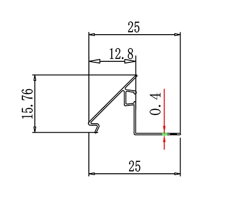
An extrusion drawing is not just a picture of the profile cross-section. It is a legal and technical contract that defines exactly what you expect your supplier to produce. Every dimension, tolerance, and note has a cost implication and a manufacturing limit.
A properly prepared drawing helps the extruder produce a suitable and economical product. This is why major standards bodies, including the Aluminum Association, have published drafting guidelines specifically for extruded products .
Step 1: Read the Title Block First
The title block is the starting point for understanding the entire drawing. It contains essential information that dictates the entire production process.
Key Items to Look For
Alloy and Temper: This is usually the first thing a production planner checks. It tells the plant which billet to use and what the exit temperature and quench settings need to be. For example, EN AW-6063-T5 specifies a common architectural alloy, while 6061-T6 indicates a stronger structural material .
Tolerance Standard: This must be stated explicitly. The choice between general and precision standards has a major impact on cost. For European projects, you will typically see EN 755-9 (general engineering) or EN 12020-2 (high precision) . For North American projects, ANSI H35.2 or ASTM B221 are common references . If the drawing does not state a standard, clarification is needed before production begins.
Drawing Number and Revision: Always verify you are working with the latest revision. Using an outdated drawing can lead to expensive tooling mistakes. You should also confirm if the drawing is a "Profile" drawing (defining the cross-section) or an "Fabrication" drawing (defining cut lengths, holes, and notches).
Step 2: Understand the Cross-Section View
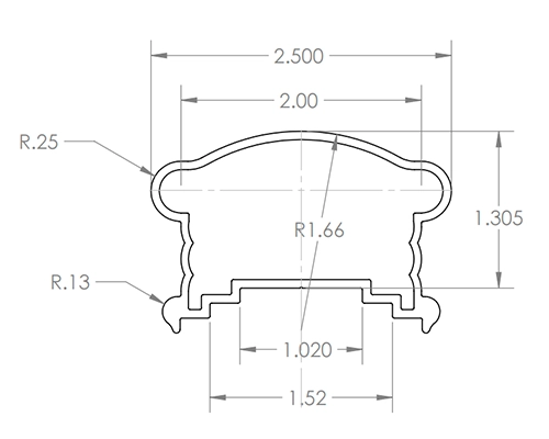
The main view on an extrusion drawing is the cross-section of the profile. This is what the part would look like if you sliced through it and looked at the end.
How to Interpret the Section
Dimension Lines with Arrows: These define the size of external and internal features. For example, 100 mm with arrows pointing to the outer edges defines the width of the profile.
Centerlines and Datum Lines: Centerlines (often shown as a dashed line with alternating long and short dashes) indicate symmetry. Datum lines (often shown with a triangle and a letter, like A) are theoretical reference points from which all other measurements are taken . A datum is the origin from which the location or orientation of part features is established. Confusion can arise if the drawing does not specify how a part is to be located; datums are how this is clarified .
Wall Thickness: These are often indicated with leader lines pointing to the specific wall. A note like 5.0 mm in a circle is a direct wall thickness measurement.
Feature Control Frame: This is a rectangular box containing geometric tolerance symbols. It specifies allowable variations in form, orientation, or position . For example, a frame might contain a symbol for "straightness" and a number 0.5 mm. This means the surface must not deviate from a perfectly straight line by more than half a millimeter.
Step 3: Deciphering the Language of Tolerances
Tolerances define the acceptable range of variation for a dimension. Tighter tolerances mean higher production costs, so it is critical to understand what is specified.
General Tolerances (Uncalled Dimensions)
If a dimension does not have a specific tolerance marked next to it, it is controlled by the "General Tolerance" stated in the title block. For EN standards, a common general tolerance for dimensions under 100mm might be ±0.5 mm.
Direct Tolerances
These are tolerances shown next to a specific dimension. For example, 100.0 ±0.2 mm indicates the dimension must fall between 99.8 and 100.2 mm.
Tolerance Standards (EN 755 vs. EN 12020)
Understanding the difference between these standards is crucial for cost control.
EN 755 is the standard for general engineering applications. It offers wider tolerances, which makes it more economical. It is best for heavy machinery, structural building frames, and hidden internal parts where tight visual precision is not critical. For a profile with a 100 mm external size and 5 mm wall thickness, EN 755 allows an external dimension tolerance of ±0.85 mm and a wall thickness tolerance of ±0.40 mm .
EN 12020 is a specialized precision standard, primarily for architectural alloys like 6060 and 6063. It offers significantly tighter tolerances—often twice as strict as EN 755—and demands a higher quality surface finish. For the same 100 mm profile, EN 12020 requires an external dimension tolerance of just ±0.45 mm and a wall thickness tolerance of ±0.25 mm .
Important Note: Not all alloys can meet EN 12020 precision tolerances. Structural alloys like 6082 or 7075 must use EN 755, regardless of the application. If you request precision tolerances for these alloys, the supplier will likely have to reject the spec or correct it .
Geometric Tolerances (GD&T)
Beyond simple size, a drawing may specify geometric tolerances for form, orientation, and location . The most common ones for extrusions are:
Straightness: Limits how much the profile can bow along its length. For a general profile, EN 755 might allow a deviation of up to 1.5 mm per meter, while EN 12020 could restrict this to 0.5 mm per meter . You will see a symbol that looks like a short, straight horizontal line.
Twist: Defines how much the profile is allowed to rotate around its longitudinal axis. For a 1-meter length, EN 755 might allow up to 1.2 mm, while EN 12020 could limit it to 0.6 mm . The symbol for twist is a curved line, often like a sine wave.
Flatness and Concavity/Convexity: Limits how much a flat surface can curve or bow from side to side. For a 100 mm wide surface, EN 755 might allow up to 0.6 mm of deviation, whereas EN 12020 halves that to 0.3 mm .
Position: Controls the exact location of features like holes or slots relative to a datum. The symbol is a crosshair inside a circle .
Step 4: Critical-to-Function Dimensions
Not all dimensions are equally important. Some are "Critical-to-Function" (CTF) because they directly affect assembly. Your drawing should make these CTF dimensions clear, often with a specific symbol like a triangle, star, or a note in the title block .
Common CTF dimensions on extrusion drawings include:
Slot Widths: The width of a T-slot or groove is often CTF because it determines how a mating part fits.
Wall Thickness at Key Points: The thickness of a wall that will be tapped or drilled is a CTF for structural strength.
Straightness and Twist: For long profiles that must fit into a rigid assembly, straightness and twist are CTF.
Features Relative to a Datum: The position of a critical hole or mounting surface relative to a datum plane is often CTF.
Step 5: Practical Tips for Reading and Using Drawings
Always Verify Alloy Compatibility
Do not specify tight precision tolerances for high-strength structural alloys like 6082 or 7075. Precision standards like EN 12020 are designed for architectural alloys such as 6060 and 6063. Requesting them for incompatible alloys will cause problems .
Check for Wall Thickness Uniformity
Extruded profiles with large differences in adjacent wall thickness are prone to distortion and twist due to uneven cooling. As a rule of thumb, maintain a wall thickness ratio below 3:1 between any two adjacent walls to ensure stable, reliable production . If your design requires high variation in wall thickness, you can optimize the transition areas, but note that design changes before tooling is cut are far less expensive than corrections after production.
Use a Hybrid Approach to Save Costs
One popular strategy is to mix standards to optimize your budget. For example, you might specify EN 755 for dimensional tolerances but EN 12020 for surface quality . This approach is practical when your profile does not require micro-precision to fit into a system but will be highly visible to customers. It gives you a high-quality finish without paying the premium for ultra-tight structural tolerances. If you use this hybrid approach, you must state it clearly on the drawing and get formal agreement from your supplier before production begins .
Review Surface Finish Symbols
The drawing should also define the required surface treatment. For anodizing, the standard is often QUALANOD; for powder coating, it is QUALICOAT . These standards define not just the finish quality but also acceptable locations for contact marks that may occur during processing. The drawing should also specify whether the finish is for the entire profile or only certain "visible" faces .
Frequently Asked Questions (FAQ)
Q: What is the difference between EN 755 and EN 12020?
A: EN 755 is the standard for general engineering applications, offering wider tolerances at a lower cost. EN 12020 is a precision standard for architectural profiles, offering tolerances that are often twice as tight and a superior surface finish, but at a higher cost .
Q: Can I specify EN 12020 tolerances for any aluminum alloy?
A: No. EN 12020 is typically only applicable to high-finish architectural alloys like EN AW-6060 and EN AW-6063. Structural alloys like 6082 or 7075 must use EN 755 . If you specify EN 12020 for these alloys, the supplier may reject the spec.
Q: What is a datum, and why is it important on an extrusion drawing?
A: A datum is a theoretical reference point, axis, or plane from which the location of all other features is measured. It eliminates confusion by defining the exact starting point for measurements .
Q: Why is maintaining a uniform wall thickness recommended?
A: Large differences in adjacent wall thickness (a ratio above 3:1) cause uneven cooling, which can lead to distortion, twisting, and structural warping of the extruded profile . Maintaining a more uniform thickness reduces these risks.
Q: What is a hybrid specification, and how can it save costs?
A: A hybrid specification combines different standards to balance cost and performance. For example, using EN 755 for dimensional tolerances (to keep tooling costs low) while using EN 12020 for surface quality (to ensure a flawless finish). This is useful for visible architectural parts that do not require extreme precision for assembly .
Q: What does the "Feature Control Frame" symbol mean?
A: It is a rectangular box containing geometric characteristic symbols (like straightness, flatness, or position) that define the allowable variation for a specific feature. It tells you not just how big or small a feature can be, but also its allowable form, orientation, or location .
Related Posts
Aluminum Extrusion Tolerance Design Guide — A must-read for engineers specifying tolerances.
How to Choose an Aluminum Extrusion Supplier — Use your drawing knowledge to evaluate supplier capabilities.
11 Silent Quality Traps in Aluminum Extrusion — Learn about defects that proper drawing interpretation can help prevent.
Aluminum Extrusion Process: 11 Key Steps Explained — Understand the manufacturing process behind the drawing.
Applications of Aluminum Extrusion in Different Industries — See how extrusions are used across construction, automotive, and electronics.
About Aluleader
With over 15 years of experience in the aluminum extrusion industry, Aluleader provides high-quality architectural profiles, industrial profiles, and furniture/decorative profiles. Our integrated capabilities—from die design and extrusion to CNC machining, surface finishing, and fabrication—ensure consistent quality across every project.
Our engineering team collaborates with clients to review and optimize drawings for manufacturability, helping you achieve the best balance of precision, quality, and cost. For project-specific questions or detailed inquiries about reading and preparing extrusion drawings, our experts are available to provide technical guidance.